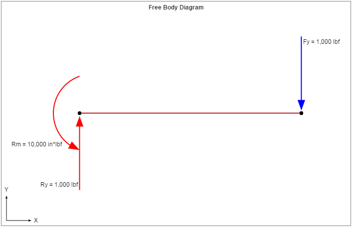
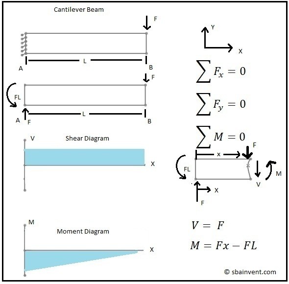
Cantilever Beam Free Body Diagram
The above beam design formulas may be used with both imperial and metric units. The tare value is 0140 v and vs is 4900 volts and the amplification factor is 500 and the gage factor is 21.
 Solved Chapter 8 Problem 2fp Solution Mechanics Of Materials 10th
Draw a free body diagram of the cantilever beam shown when fixtured.
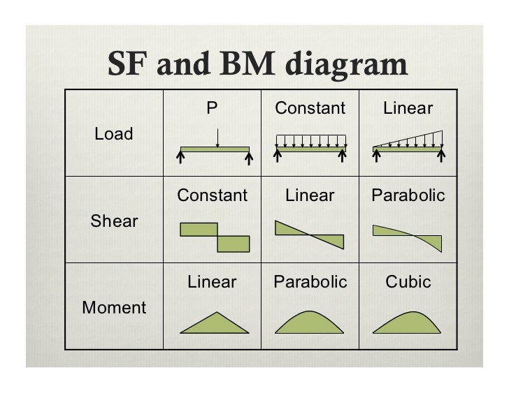
Cantilever beam free body diagram. Okay and were just the body of interest in this case is this beam up here which is. Displays a cantilever beam subjected to a point load of 20 n at free edge of the beam in downward direction. Welcome to our free online bending moment and shear force diagram calculator which can generate the reactions shear force diagrams sfd and bending moment diagrams bmd of a cantilever beam or simply supported beam.
A fbd is a convenient method to model the structure structural element or segment that is under scrutiny. E modulus of elasticity psi or mpa. All the reaction components will be experienced only on the fixed end.
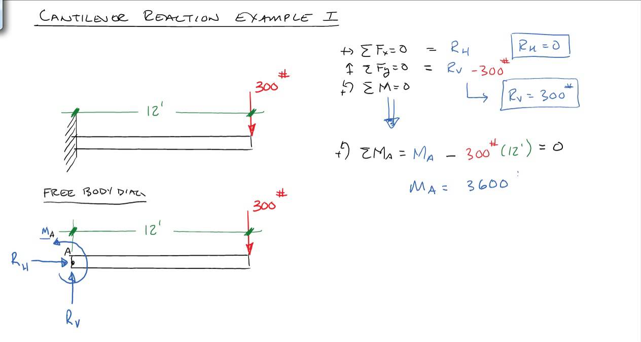
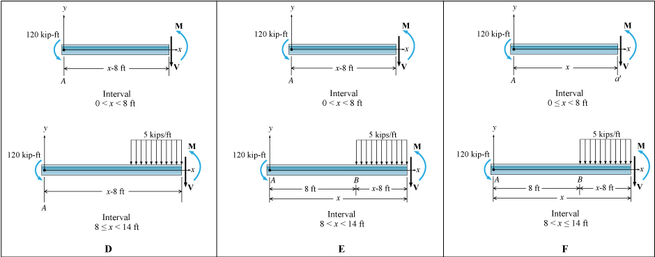
Rigid body systems asimple supported beam a cantilever beam. If a beam is cantilevered it has a fixed support at one end which is the right end for this beam the beam weighs 150 lbft and the weight of the beam acts through its centroid. Bmd bending moment diagram.
Examples from bio medical engineering human. Sfd shear force diagram. In this case ive got whats called cantilever beam.
Beam free body diagram. Bmd bending moment diagram. The length of the.
Cantilever free body diagram example statics spoon feed me. E modulus of elasticity psi or mpa. A simply supported beam a simply supported beam.
A beam supported by a column and a knee frane hinged cantilever beam with cable support. A free body diagram is a graphic dematerialized symbolic representation of the body structure element or segment of an element in which all connecting pieces have been removed. Drawing a free body diagram and sketch free body diagrams for some bodies.
Its a really important tool so were going to spend some time on it to cement. In the case of cantilever shown in figure 5 1a there. As shown in the free body diagram in figure 5 1b.
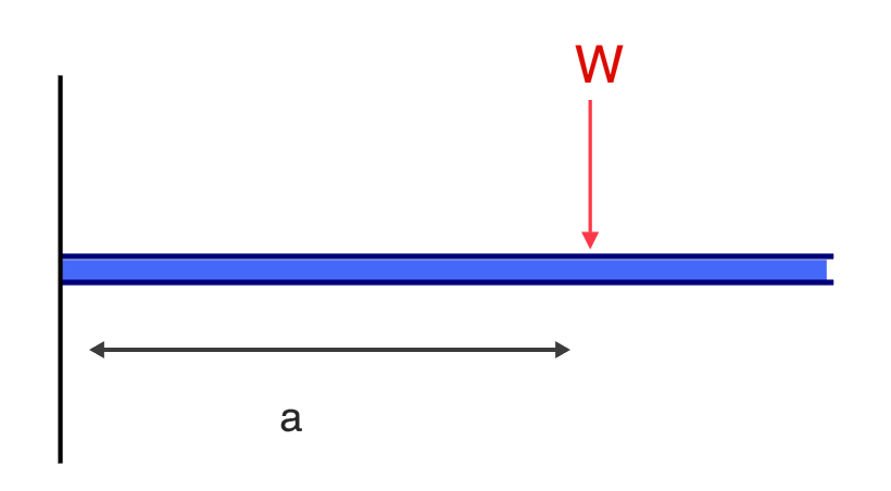
Fbd free body diagram. Draw the free body diagram fbd of the uniform cantilever beam shown. The cantilever is a beam which has one end free and the other is fixed.
The above beam design formulas may be used with both imperial and metric units. Fbd free body diagram. Sfd shear force diagram.
A mast with a platform. As with all calculations care must be taken to keep consistent units throughout with examples of units which should be adopted listed below. Actual structure a truss free body diagram.
Include all relevant geometry with consistent notation. About the beam calculator. As with all calculations care must be taken to keep consistent units throughout with examples of units which should be adopted listed below.
 Shear Force And Bending Moment Diagrams Wikiversity
 Mechanics Of Materials Bending Normal Stress Mechanics Of
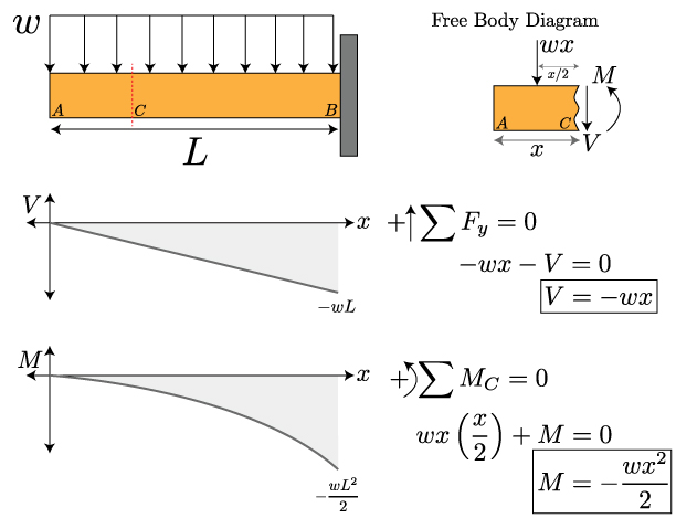
 Mechanics Of Materials Chapter 4 Shear And Moment In Beams
 Solving Reactions For A Cantilevered Beam Youtube
 Beam Analysis Validation Mechanicalc
 Cantilever Beam Point Load At Any Point
 Beam Bending Diagram Save Organisedmum De
 Cantilever Beam Skyciv
 Solved Shear And Bending Moment Diagrams Learning Goal T
 Lecture 9 Shear Force And Bending Moment In Beams
 Solved Draw A Free Body Diagram And Identify All Loads On
 Lecture 23 And 24
 Shear Force And Bending Moment Diagrams Wikiversity
 Shear And Moment Diagrams S B A Invent
 Beam Bending Diagram Save Organisedmum De
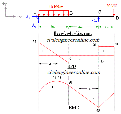
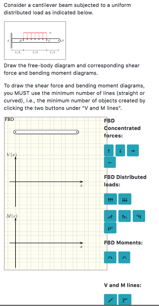 Solved Consider A Cantilever Beam Subjected To A Uniform
 How To Draw Bending Moment Diagrams Skyciv
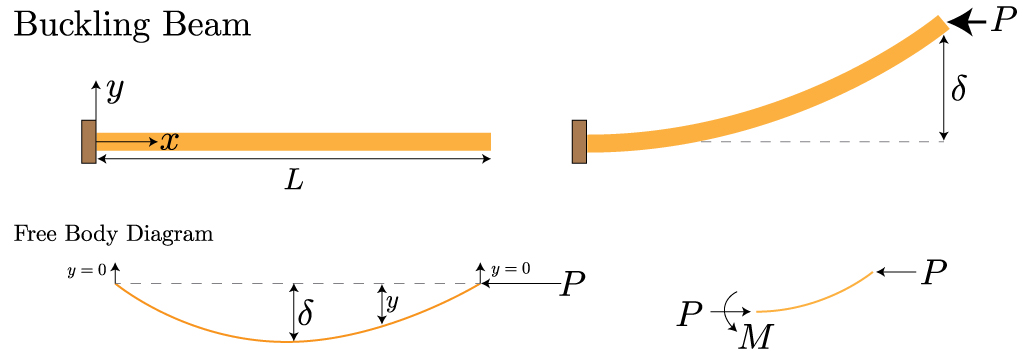
Mechanics Of Materials Beam Buckling Mechanics Of Slender
 How To Draw Shear Force Bending Moment Diagram Simply Supported

0 Response to "Cantilever Beam Free Body Diagram"
Post a Comment