Draw The Shear Diagram For The Compound Beam Which Is Pin Connected At B
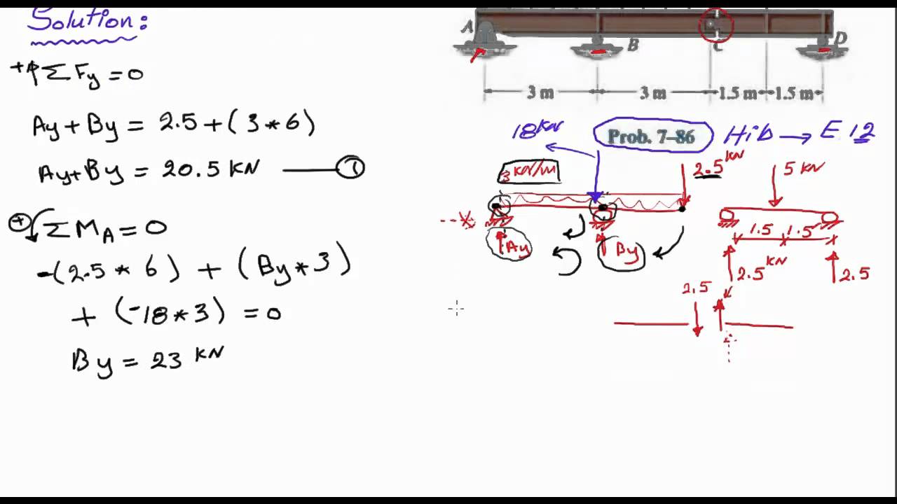
Solution 43 1 simple beam. But with the given loading it is balanced and will remain as shown if not disturbed 11 25 draw the shear and moment diagrams for the beam and determine the shear and moment in the beam as functions of x where 12 m x 3 m.
 Solution To Problem 438 Relationship Between Load Shear And
B determine the equation of internal forces of member acd and draw its diagram.

Draw the shear diagram for the compound beam which is pin connected at b. Download with google download with facebook or download with email. Draw the shear and moment diagrams for the beam. Reset help add vertical line off delete add segment v 6 kip 8 kip 4 ft 6 ft 4 ft 4 ft 15 6 submit my answers give u.
Engineering mechanics homework8 11 7 draw the shear and moment diagrams for the compound beam which is pin connected at b. In the frame shown determine the internal forces a in member acf at point j and in member bcd at point k. Skip navigation sign in.
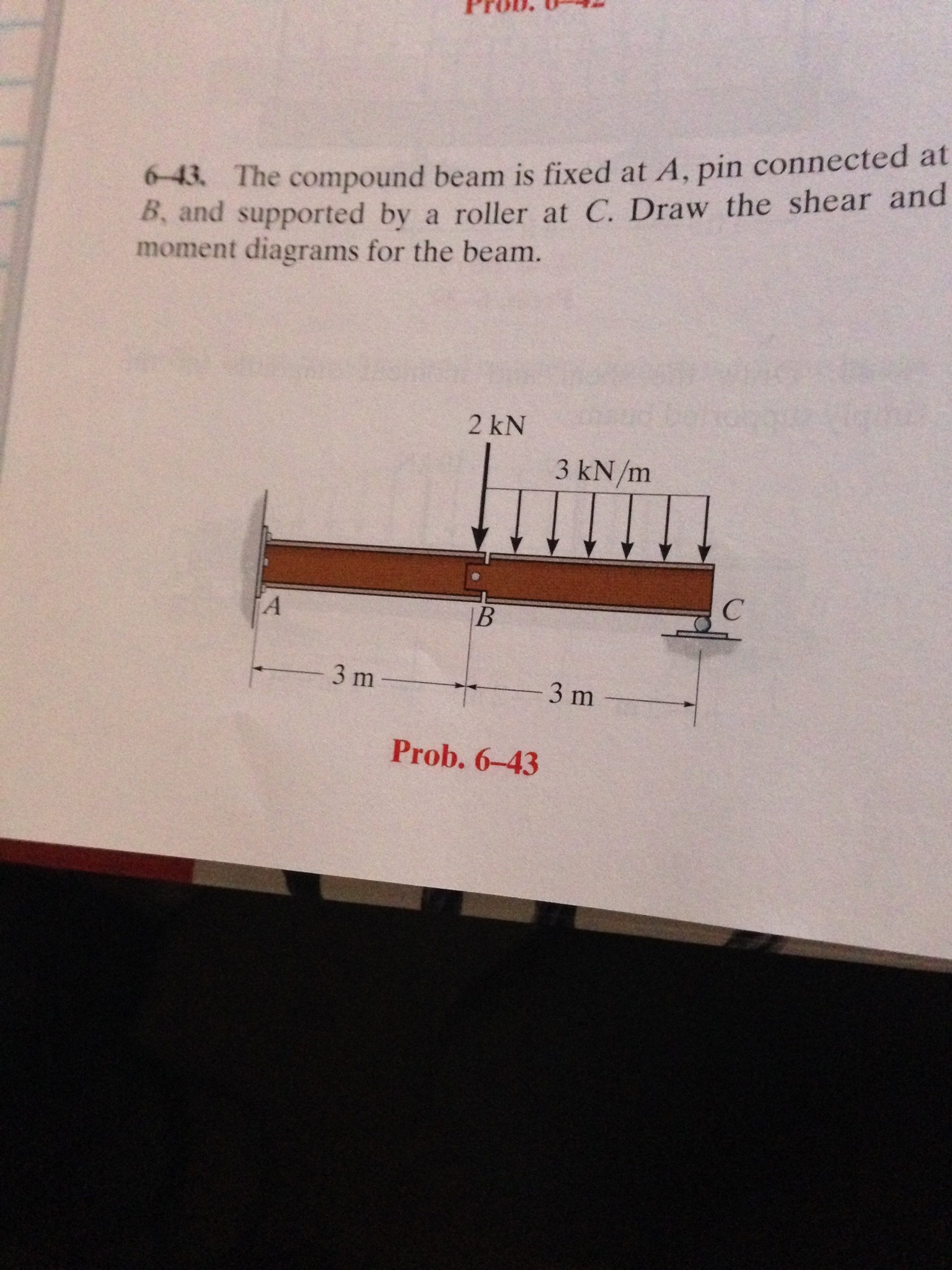
Draw the shear and moment diagrams for the beam. Draw the shear and moment diagrams for the beam. Show transcribed image text the compound beam is fixed at a pin connected at b and supported by a roller at c.
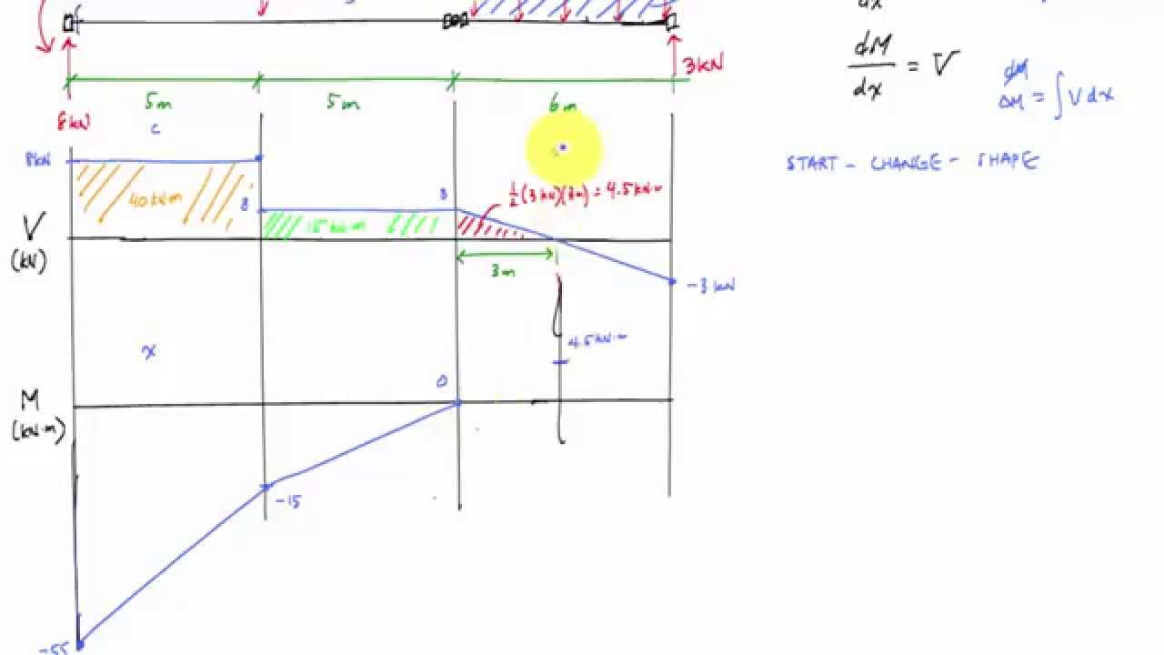
This structure is not fully stable. Drawing shear force and bending moment diagram for a compound beam. The beam consists of two segments pin connected at b.
700 lb 8 ft 4 ft 6 ft 9400 lbft 150 lbft v lb xft xft m lbft 1017 0 317 583 8 141 18 8 9400 1267 162 800 334 9 15. The reactions and the forces acting on each member of the frame are determined. Assuming that frame can be treated as a rigid body.
Draw the shear and moment diagrams for the beam. 1 answer to the compound beam is fixed at a pin connected at b and supported by a roller at c. 100 17 ratings or.
Drawing shear force and bending moment diagram for a compound beam. Show transcribed image text problem 67 part a draw the shear diagram for the compound beam which is pin connected at b click on add vertical line to add discontinuity lines. The compound beam is fixed at a pin connected at b and supported by a roller at c.
Shear forces and bending moments problem 43 1 calculate the shear force v and bending moment m at a cross section just to the left of the 1600 lb load acting on the simple beam ab shown in the figure. 2654211 home questions engineering civil engineering civil engineering others the compound beam is fixed at a pin connected at. Then click on add segment button to add functions between the lines.
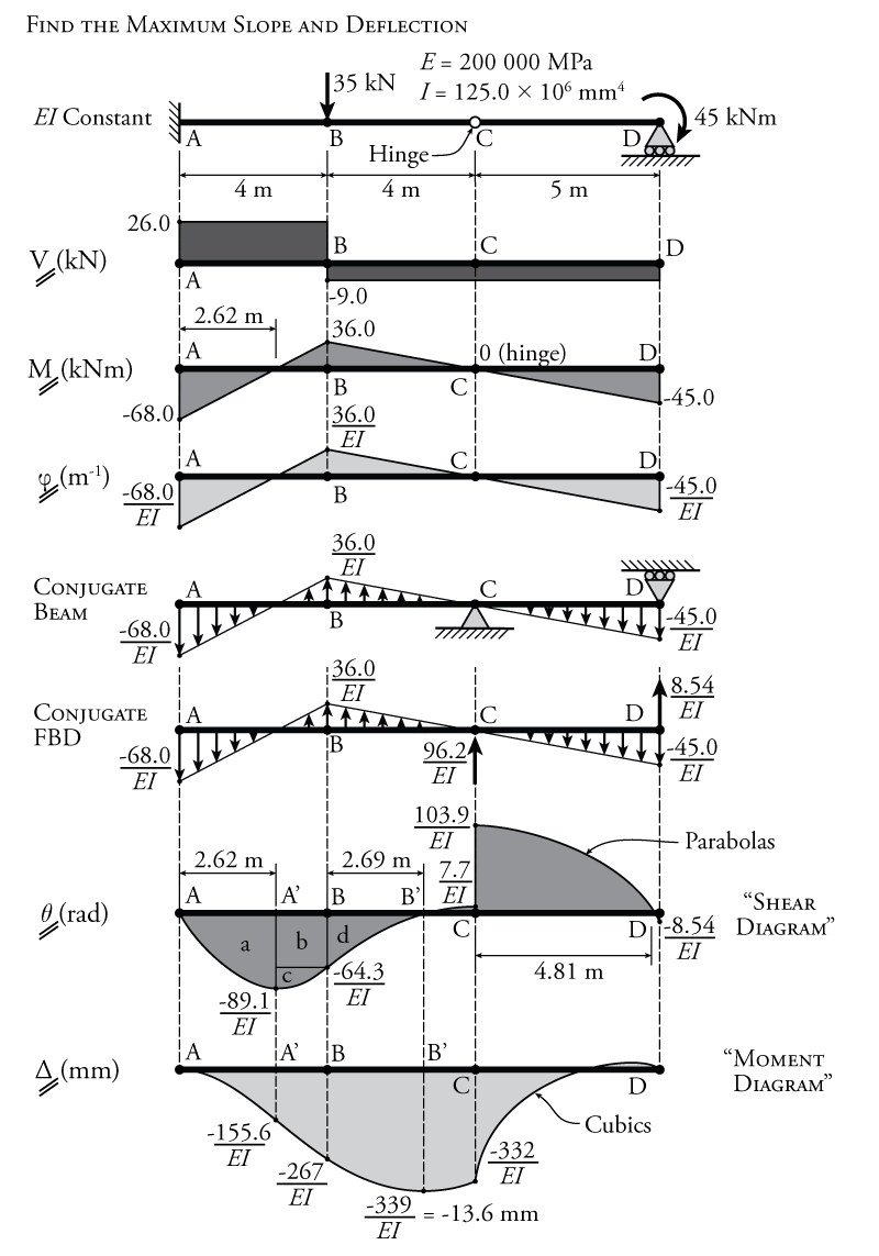
 Shear And Moment Diagram For Beam With Hinge Mechanics Of
Mechanics Of Materials Chapter 4 Shear And Moment In Beams
 Sm Ch 11 Jose Sinta Academia Edu

 Solved The Compound Beam Is Fixed At A Pin Connected At B And
Hibbeler Chapter 6 Part 1 463 486 Qxd
Book Solution Mechanics Of Materials Russell C Hibbeler S C
 Development Of Steel Beam To Column Connections Using Sfrcc Slabs
 English Compound Beam Shear And Moment Diagram Youtube
 Extra Examples Ppt Video Online Download
Solved Draw The Shear Force And Banding Moment Diagram Of The
 Solved The Compound Beam Is Fixed At A Pin Connected At
 Modeling Of Coupling Beams In Shear Walls Perform 3d Computers
 Hibbeler Statics Solution Chapter 7 1
250 7500 0 2 V X N
329 6 1 Draw The Shear And Moment Diagrams For The Shaft The
 Engineering Mechanics Homework8 Engineering Mechanics Homework8 11
11 2 1 The Steel Framework Is Used To Support The Reinforced Stone
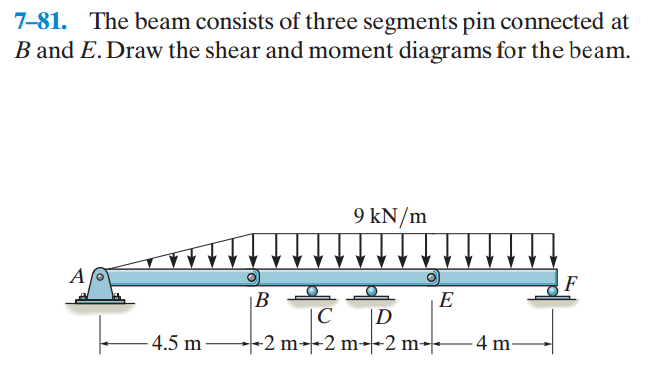 Solved 7 81 The Beam Consists Of Three Segments Pin Conn
0 Response to "Draw The Shear Diagram For The Compound Beam Which Is Pin Connected At B"
Post a Comment