Push To Exit Button Wiring Diagram
Motion sensors can take over the job of push to exit buttons. Push to exit button by enforcer brandmotion sensors.
 Bluetooth Access Control Use Phone To Open Door Systems Deadbolt
You could also use a wireless receiver and transmitter to control break or make the loop.
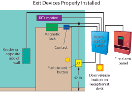
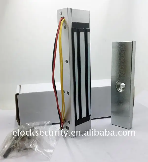
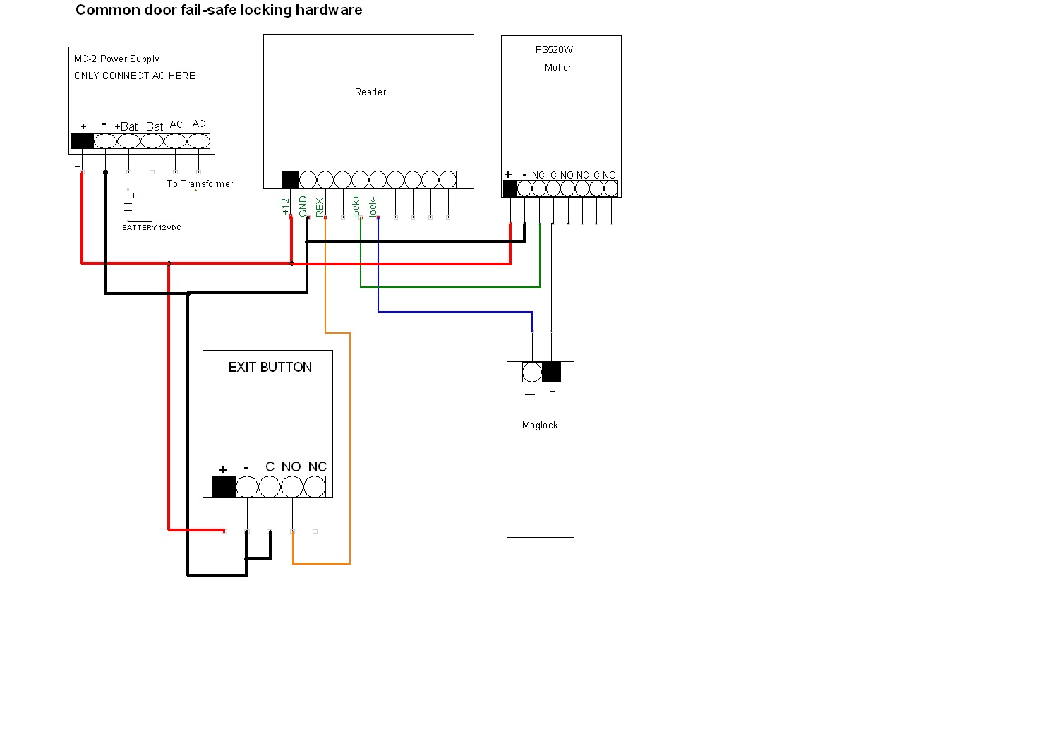
Push to exit button wiring diagram. Connect an extra piece of wire to the positive on the magnetic lock 25. Figure 1 shows the color coded identification of the wires and a typical wiring diagram showing a power supply motion detector push button and magnalock so as to comply with the boca code for access controlled egress doors. Wiring diagram electromagnetic door lock em lock push button power supply 12v carane ngonek kunci magnet.
L the schematic or line diagram includes all the components of the control circuit and indicates their. Using a wireless transmitter and receiver to release an electromagnetic lock. Electromagnetic lock or a fail safe strike the strike is polarity insensitive push button nc depressing the push button or activating the keypad would open the circuit stopping the flow of electricity and causing the magnet or strike to release.
Wiring diagram button template product overview videos all essex videos. They are mounted right over the door at the inside of the door frame. Single gang 2 square push button spdt or dpdt.
The dpst contacts switch when the button is depressed and return when it is released. The model pb5 is a spring loaded momentary 2 diameter illuminated exit button mounted on a stainless steel single gang outlet box cover. The entry switch could be a key switch keypad or other access control device.
Two are for the application of constant power and two are for control of the magnetic lock. The exit switch could be a palm button touch bar or motion sensor. Typical wiring diagrams for push button control stations 3 genera information at each circuit is illustrated with a control circuit continued schematic or line diagram and a control station wiring diagram.
Bring the wire from the common on the push button to the negative on the magnetic lock 24. Wiring instructions fail safe strike with button and keypad wired in series. The contacts are ul listed with 10 amp capacity.
Due to their motion sensor they can trigger motion and thus unlock the door right when you walk up to the door to exit the space. Essex electronics stainless steel vandal resistant request to exit buttons can be used to control an automatic door electric lockstrike magnetic lock or any electrically controlled device.

 Elock Wiring Diagram 20 Wiring Diagram Images Wiring Diagrams
Hone Your Access Control Knowledge
Installation Operating Instructions 4399 Exit Button
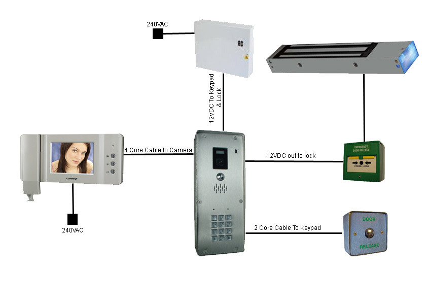 Wiring Door Entry Systems
 Test Light Wiring Diagram 0f Imixeasy De
 Access Control Products Devices Card Reader Systems Kisi
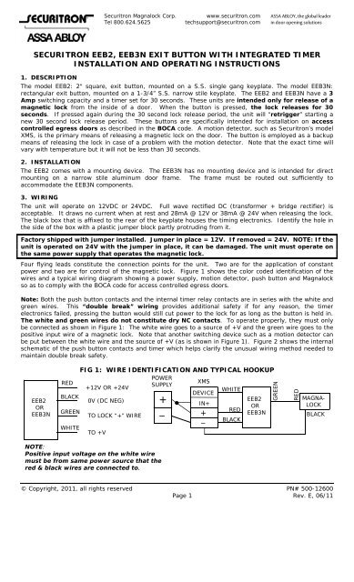 Securitron Eeb2 Eeb3n Exit Button With Securitron Magnalock
 Access Control Wikipedia
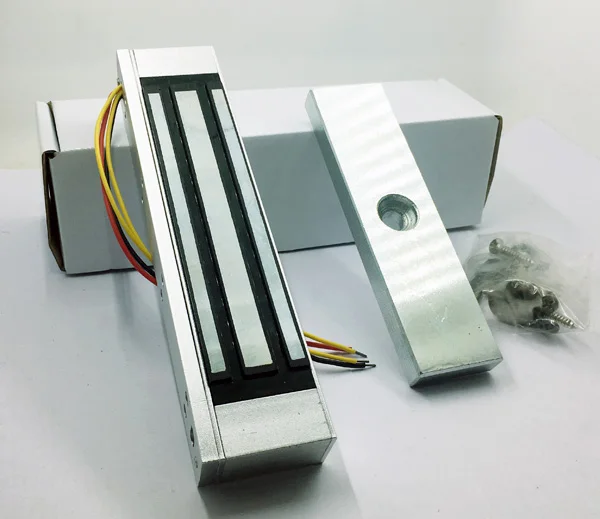
 How To Install Mag Lock With Keypad And Exit Bottom Magmag 2500
 Amazon Com Power Supply Box With Battery Interface 2 Door System
 970 Illuminated Exit Switches Rci Dormakaba
 Video On How To Wire A Three Way Switch

 Installation Schematics And Wiring Diagrams

 Amazon Com Fingerprint Pin Access Control Systems 600lbs Mag

0 Response to "Push To Exit Button Wiring Diagram"
Post a Comment