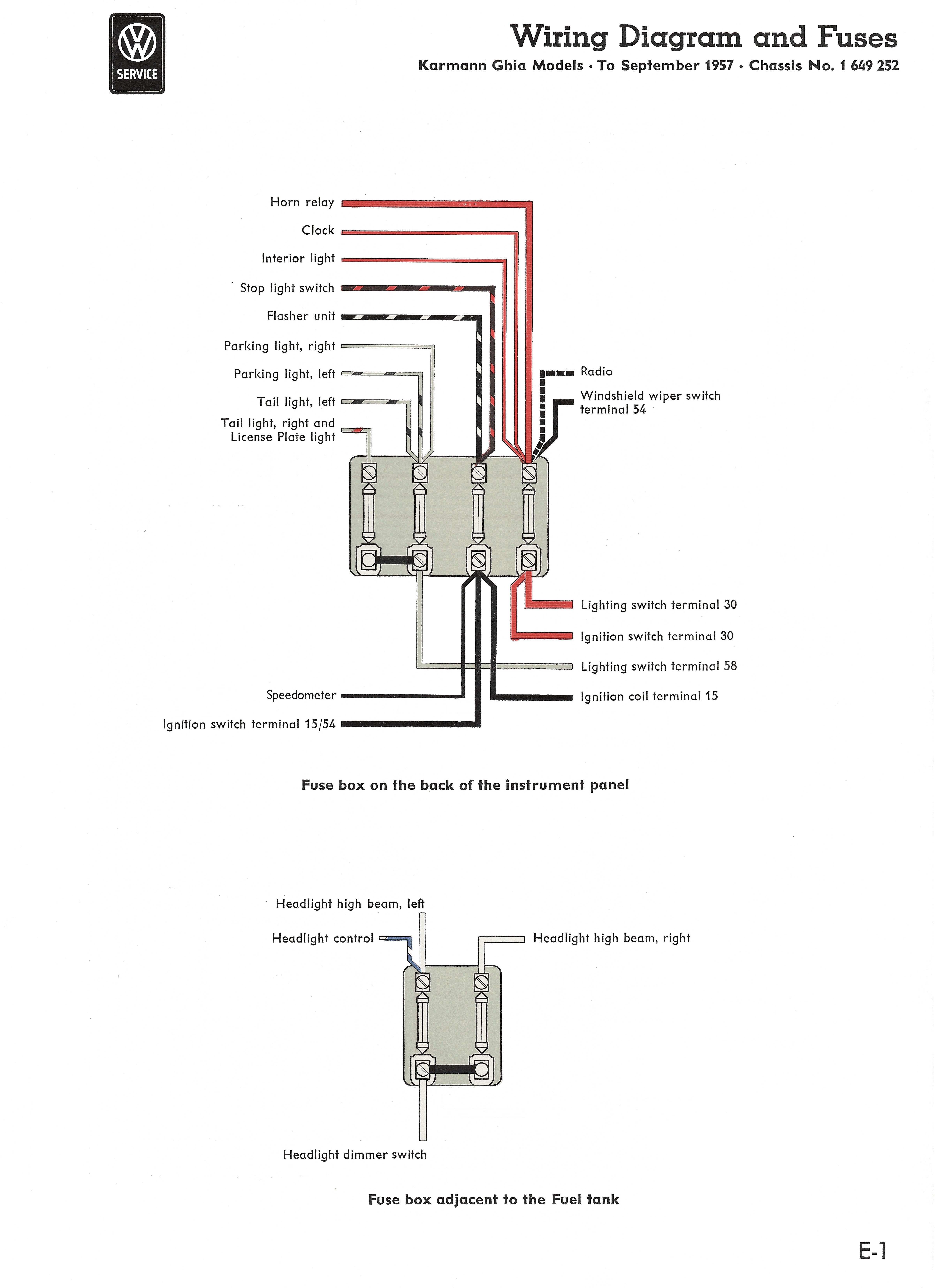
7 Terminal Ignition Switch Wiring Diagram
Once you attach the ground power wires to the switch double check me on the other terminals prior to wiring it to vehicle to make sure your modified vehicle is the same way. A magneto system requires the two m terminals open circuit for run and closed circuit to stop.
 7 Terminal Ignition Switch Wiring Diagram Ignition Switch System
Universal ignition switch wiring diagram.

7 terminal ignition switch wiring diagram. See tables below for switch position descriptions and wiring information. 4 position universal ignition switch with chrome bezel and die cast body rated at 30a. 4 wire ignition switch diagram wiring diagram database wiring diagrams ford starter solenoid manual e books mopar ignition switch wiring diagram 4 wire ignition switch diagram.
White s terminal. I am 90 sure i got it correct. There is a big difference between wiring for a magneto system as most two strokes are and a battery ignition system as io and inboards are.
Lawn mower ignition switch wiring diagram moreover lawn mower ignition switch wiring diagram additionally craftsman lawn mower wiring diagram also john deere mower drive belt diagram also john deere wiring diagrams. Black wire to ground g terminal. Turn signal light headlight parking or city light front turn signal light ignition switch dimmer switch turn signal switch horn switch resistor gear position switch magneto tailbrake light cdi unit ignition coil.
2 black wires m terminal. Your wiring diagram does not show a. Craftsmanayp 7 wire ignition switch i am looking for which terminals lead to on the mower and also what pins should have continuity in each switch position.
It is a 4 position switch with 7 terminals that are marked m l b s y g a. 1220 automotive electrical systems table 7. Find this pin and more on mowers by troy norris.
2 red wires b terminal. Does anyone know the color code for ignition switch block for craftsman riding mower modelnnn nn nnnnthere is a five pin block and five colored wires but do not know which color goes where. Remove 3 ignition switch mounting screwscarefully pull switch away from columnrelease 2 connector locks on 7 terminal wiring connectorthen disconnect from ignition switchrelease connection lock on 4 terminal connectorthen disconnect from ignition switch.
Requires a 19mm panel hole with 176mm anti rotation flats. Ok now we talk about the wiring diagrams inside this suzuki gn 400 lighting wiring diagram you will find parts like. Evinrude tachometer wiring 99kenmolpde evinrude wiring color code wiring diagram database rh 7 condoteltayho evinrude tachometer wiring diagram evinrude.
Supplied with 2 unique keys. Line from battery ii positive terminal 31 return wire from battery negative or ground direct return wire to battery negative or ground via switch 31 b or relay switched negative. Ignition switch output 15a output at the series resistor.
Be careful using the word universal ignition switch. The bat acc and ign terminals have twin parallel contacts and the st terminal is a single contact. Here is the wiring diagram for the ignition switch.
On john deere scotts mower wiring diagram. Terminal designations according to din 72552.
 Mustang Dash Wiring Diagram Free Download Wiring Diagram Schematic
 Ignition Switch Diagram Best Part Of Wiring Diagram
 Disconnect Switch Wiring Diagram As Well Ignition Kill Switch Wiring
 Briggs And Stratton Ignition Switch Diagram Www Toyskids Co
 Lawn Mower Ignition Switch Wiring Diagram Moreover Lawn Mower
 Ignition Switch Schematic 1 Ulrich Temme De
 Sym Cdi Wiring Diagram Best Part Of Wiring Diagram
 7 Way Wiring Diagram Inspirational Ignition Switch Pollak 6 Terminal
 45 Harley Wiring Diagram Schematic Diagram
 Briggs And Stratton Ignition Switch Diagram Www Toyskids Co
 Mini Chopper Wiring Diagram For Ignition Switch Wiring Schematic
 Switch Wiring Schematic Best Part Of Wiring Diagram
 Flow Switch Wiring Diagram Best Wiring Library
 Gm Ignition Switch Wiring Diagram Impala Automotive Pollak Marine
 6 Post Switch Wiring Diagram Online Wiring Diagram
 7 Terminal Ignition Switch Wiring Diagram Reference Turn Signal
 7 Terminal Ignition Switch Wiring Diagram Fresh 3 Position Ignition
 7 Spade Trailer Wiring Diagram Schematic Diagram
 Dorman 85936 Wiring Diagram Fresh Pollak Ignition Switch 6 Terminal
 Ignition Switch Diagram Best Part Of Wiring Diagram
 Ford 3000 Ignition Switch Diagram Schematic Diagram

0 Response to "7 Terminal Ignition Switch Wiring Diagram"
Post a Comment