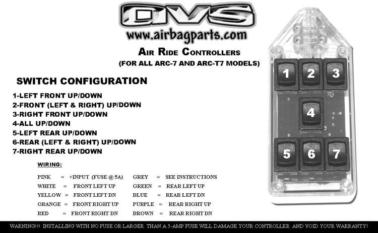
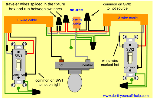
Air Ride Switch Box Wiring Diagram
Tow assist tank wiring plumbing diagram. 2 large 12 pole switches 4 smaller 3 pole switches and 4 smaller 6 pole switches.
Airbag Wiring Diagram Air Ride Free Wiring Diagram For You
Air suspension installation and air bag instruction manuals to help you install or replace your air ride parts.

Air ride switch box wiring diagram. Air ride suspension switch box. Air ride switch box avs 7 rocker billet air bag suspension system controller. How to wire up a 12 volt air compressor for air ride.
Skip to main content. Tow assist wiring and plumbing diagram. This is a image galleries about air ride switch box wire diagramyou can also find other images like wiring diagram parts diagram replacement parts electrical diagram repair manuals engine diagram engine scheme wiring harness fuse box vacuum diagram timing belt timing chain brakes diagram transmission diagram and engine problems.
Source black 9 switch series rocker avs and avs switch box wiring diagram. How i made my switch box. How to install onboard air compressor wiringmounting viair 444c source kit system in.
How to make an air ride switch box earthscraper69 minitrucker4life. And im working on a 3rd diagram showing switch wiring that overlays with the valve diagram. Connect the black wires pin 1 pin 3 to ground.
Tow assist afc valves dual zone tank wiring plumbing diagram. Connect the red wire pin 2 to constant 12v. 1this output is only designed to supply power to a compressor that requires less than 40 amps.
Air ride suspension vu4 wiring harness connects to any avs switch box. How to make an air ride switch box. An air ride switch box is a necessary component for all air suspension systems they are what you use to control your air valves to inflate and deflate your air bags.
Air ride switch wiring help lots of switches so im building a air system for my rat rod on a 68 c10 chassis. Skip navigation sign in. All are momentary 2 way switches.
Installing more of my air ride set up. Connect the yellow pin 4 to the compressor less than 40amp or compressor relay over 40amp draw. Tow assist wiring and plumbing diagram no tow kit.
Since each switch in your switch box controls a particular function like inflating or deflating dumping your front bags or rear bags. I bought a switch box that im assuming was ment for hydraulics. There are 10 total switches.
Find great deals on ebay for air ride switch box.
Diagram Wiring Box Switch Hydraulic 10 Schematic Diagram
1997 Bonneville Air Ride Wiring Diagram Free Wiring Diagram For You
 Air Ride Solenoid Wiring Diagram Wiring Schematic Diagram
1984 Lincoln Continental Wiring Diagram Manual Also Mini Cooper
 Air Ride Compressor Wiring Diagram Inspirational Air Ride Switch Box
 Air Ride Switch Box Wiring Great Installation Of Wiring Diagram
Best Porter Cable Air Compressor Wiring Diagram Vr5 8 Air Compressor
 Air Ride Switch Box Wiring Diagram Wiring Diagram And Schematics
Air Ride Switch Box Wiring Diagram Guide To Understanding Air
 Air Ride Suspension Control Hackster Io
 Dimmer Switch Wiring Diagram Moreover Leviton 3 Way Switches Wiring
 Gallery Of Air Ride Switch Box Wiring Diagram Wire
Air Ride Switch Wiring Diagram Www Toyskids Co
Air Suspension Wiring Diagram 5a2262785f546 For Ride Switch Box 834
 Gallery Of Air Ride Switch Box Wiring Diagram Wire
 Air Ride Technologies Wiring Diagram Schematic Diagram
Air Ride Switch Box Wiring Diagram Simple Square D Air Pressor
Avs 3 Switch Box Wiring Diagram Great Installation Of Wiring Diagram

0 Response to "Air Ride Switch Box Wiring Diagram"
Post a Comment