State Table And State Diagram
A state table is essentially a truth table in which some of the inputs are the current state and the outputs include the next state along with other outputs. D q 00 01 11 10 00000 ab x d a 00 01 11 10 00000 ab x d b 00 01 11 10 00000 ab x z 10111 11000 10011 d aaxbx d babx zax.
 Finite State Machine Design Techniques For Digital Systems
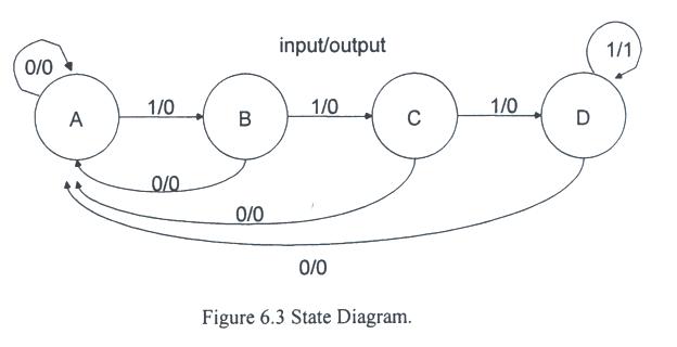
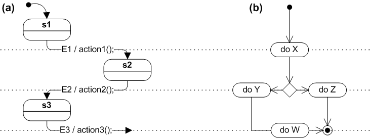
Another state diagram example.

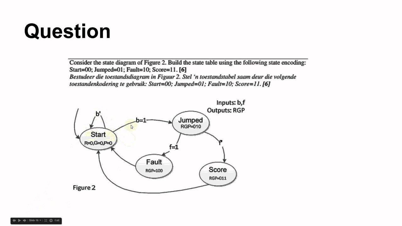
State table and state diagram. This is one of a series of videos where i cover concepts relating to digital electronics. State diagrams and state tables. Lets say youve identified your object and your object states now its time to identify all of your transitions.
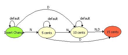
A state table is one of many ways to specify a state machine other ways being a state diagram and a characteristic equation. Transitions are shown by arrows labelled with the particular input causing the change of state. State 2 this state is entered when the user has pressed the button to turn on the light the light has turned on and the system is waiting for the user to release the button.
Releasing the button sends the system to state 3. All states are stable steady and transitions from one state to another are caused by input or clock pulses. Each internal state is represented in the state diagram by a circle containing an arbitrary number or letter.
After clock state transition clock 1 flip flop 2 states 2 flip flops 4 states 3 flip3 flip flops 8 statesflops 8 states 4 flip flops 16 states. Before clock next state. They are also very similar in discovering the states for your object.
The state diagram isq qnext s r0 0 0 x0 1 1 01 0 0 11 1 x 0 6. In this diagram a state is represented by a circle and the transition between states is indicated by directed lines or arcs connecting the circles. Circuit state diagram state table.
The sr flip flop state table. No cable box required. State tables 2 state diagrams 2.
Circuit state diagram state table example. The future of live tv with 60 channels. In this video i talk about state tables and state diagrams.
Once the button is pressed the system is moved to state 2. Flip flop output combination present state. State tables and state diagrams are very similar in how you decide that you need one for a business object.
Circuit state diagram state table. State diagram state tablestate table state tablestate diagram îcircuit d ff characteristic eq. Characteristic equation qnext d d flip flop symbol characteristictable.
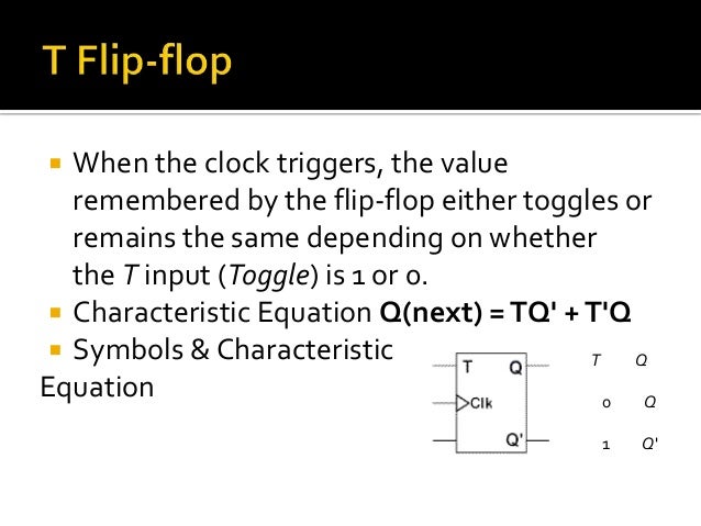
When the clock triggers the valueremembered by the flip flop becomes thevalue of the d input data at that instant. In addition to graphical symbols tables or equations flip flops can also be represented graphically by a state diagram.
State Transition Diagram
 Sequence Detector
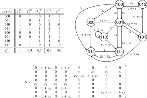
 A The State Table And State Diagram Of C1 Ffl The Symbol X
 An Example Of Truth Table State Transition Diagram An Open I

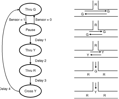 Traffic Light Controller Finite State Machines Electronics Tutorial
 Solved Derive The State Table And The State Diagram Of The
Circuit State Diagram State Table Circuits With Flip Flop
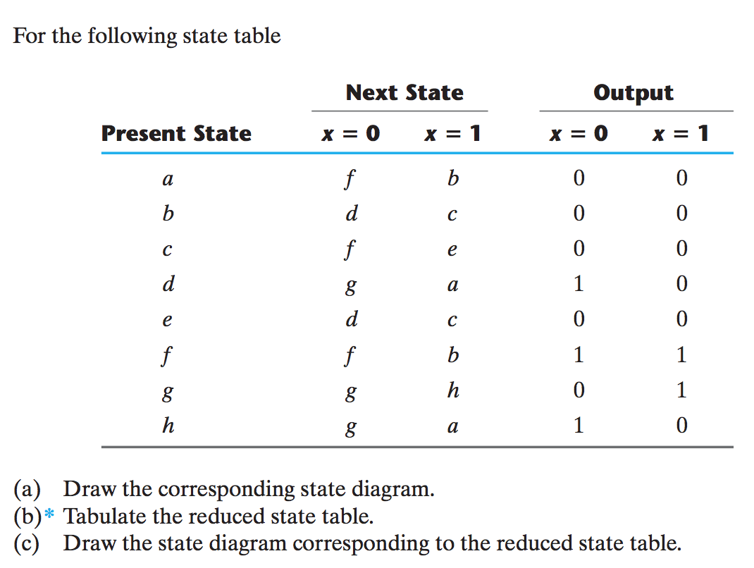 Solved For The Following State Table A Draw The Correspo


 Fsm Design Procedure State Diagram To Encoded State Transition Table
 State Diagram And State Output Table Of A Simple 4 Bit Sequence

 Finite State Machines Creation Of A State Table Youtube
 Digital Logic State Tables And State Diagrams Youtube

 Flip Flop S State Tables Diagrams


 State Diagram Wikipedia
0 Response to "State Table And State Diagram"
Post a Comment