Consider The Circuit Diagram In The Figure
For r1 r2 r3 1 ohm r4 r5 r6 2 ohm and e 1 v. By a circuit the sum of these potential differences must be zero.
 Moore And Mealy Machine Design Procedure
Calculate the power delivered to each resistor in the circuit shown in figure p2131.
Consider the circuit diagram in the figure. Consider the circuit shown in the figure below where c1 400 µf c2 700 µf and δv 180 v. Consider the arrangement shown in the diagram. B find the potential difference across the 3 ω resistor.
A conducting bar slides along a u shaped conducting r. In the circuit shown in the figure four identical resistors labeled a to d are connected to a battery as shown. Consider the following circuit diagram.
S1 and s2 are switches. Draw a circuit diagram. Switch s1 is then opened and the charged capacitor is connected to the uncharged capacitor by closing s2.
While kirchhoffs junction law is needed only when there are one or more junctions in a circuit kirchhoffs loop law is used for analyzing any type of circuit as explained in the following tactics box. If an answer is a direction up down left right in or out give an explanation justifying your answer. Consider the circuit shown in figure p2129.
Show transcribed image text 13 problem 5. 7 4 5 6. This is where i am stuck.
A find the current flowing through the 5 ω resistor. 180 v v r 4 400 r 1 200 r 2 300 3 100 label the voltage v 180 v and the resistors. I know that i am supposed to solve.
R 3 100 v 250 v. Modify the program circuit1 to solve the circuit in problem 22 figure 28 31 of the textbook by fishbane et al. Tactics box 231 using kirchhoffs loop law 1.
When the bar is at position x what is the magnetic flux through the closed circuit. Findathe current in the r 1 20 resistor andbthe potential di erence between points aand b. C find the power dissipated in the 8.
Capacitor c1 is first charged by closing switch s1. Modify the program circuit1 and solve the circuit shown in figure 28 12 of the textbook by fishbane et al. Express all of your quantitative answers in terms of some or all of w x v andor b only.
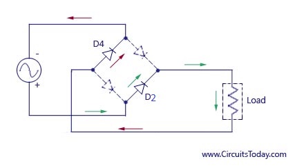 Full Wave Rectifier Bridge Rectifier Circuit Diagram With Design
 Ph203 Chapter 23 Solutions Tactics Box 23 1 Using Kirchhoff S Loop Law
 Multi Loop Circuits And Kirchoff S Rules
 3 6 Logic Representations And Circuit Design Introduction To
Physics Laboratory Manual Phyc 10190 2014 2015
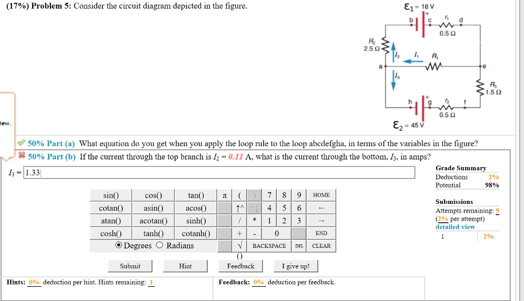 Solved 17 Problem 5 Consider The Circuit Diagram Depi
 Draw Circuit Diagram Showing A Dry Cell Connected To A Bulb Through
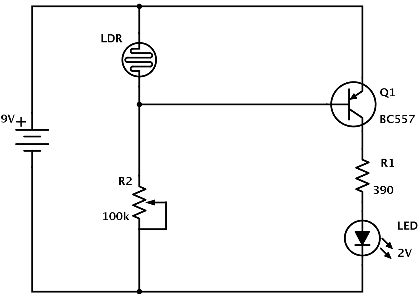 Ldr Circuit Diagram Build Electronic Circuits
 Superposition Theorem In Electric Circuits
Computer Setup
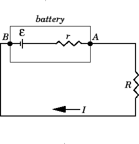 Emf And Internal Resistance
 Get Answer Consider The Volt Ampere Characteristic Of An Ideal 10
 Series Parallel Circuits Department Of Chemical Engineering And
 Planet Analog Articles Clocking Requirements For High Speed Data
 Capacitors Learn Sparkfun Com
 Pulse Circuits Bistable Multivibrator
 Schematic Diagram Of The Winner Take All Circuit For Analysis Of The
 Schematic Diagram Of A Two Neuron Winner Take All Circuit Now
 Schematic Diagram Of The Winner Take All Circuit For Analysis Of The
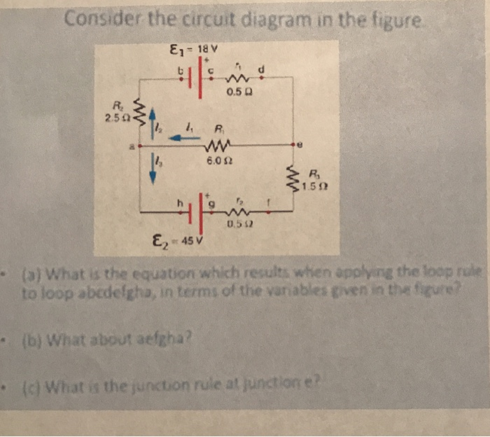 Solved Consider The Circuit Diagram In The Figure 022 0 5
 Adjustabledcvoltageregulatorcircuitusingic7805 1 Wiring Diagram
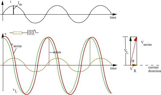 Ac Circuits Alternating Current Electricity
 Monostable And Astable Circuits


0 Response to "Consider The Circuit Diagram In The Figure"
Post a Comment