Water Treatment Process Flow Diagram
Dr a p robertson. Sewage water can travel towards treatment plants via piping and in a flow aided by gravity and pumps.

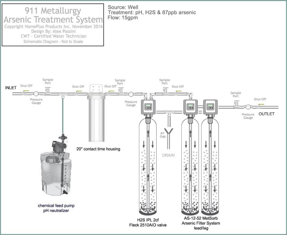
With arsenic and uranium contamination concentrations are important.

Water treatment process flow diagram. Granular activated carbon contactors. Biological wastewater treatment with activated sludge process. Civil and environmental engineering stanford duration.
Cooling process flow diagram. The solids attached to the carbon bed hamper further adsorption process. Process and instrument diagram.
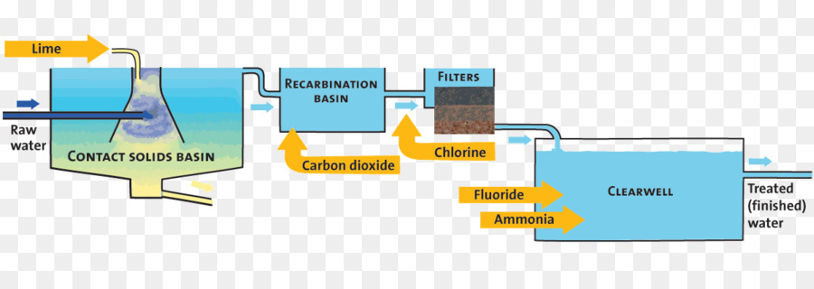
Surface water treatment plant flow diagram. By use of fine screening even floatable matter and algae are removed. Here is a simple water treatment pfd example created by edraw max.
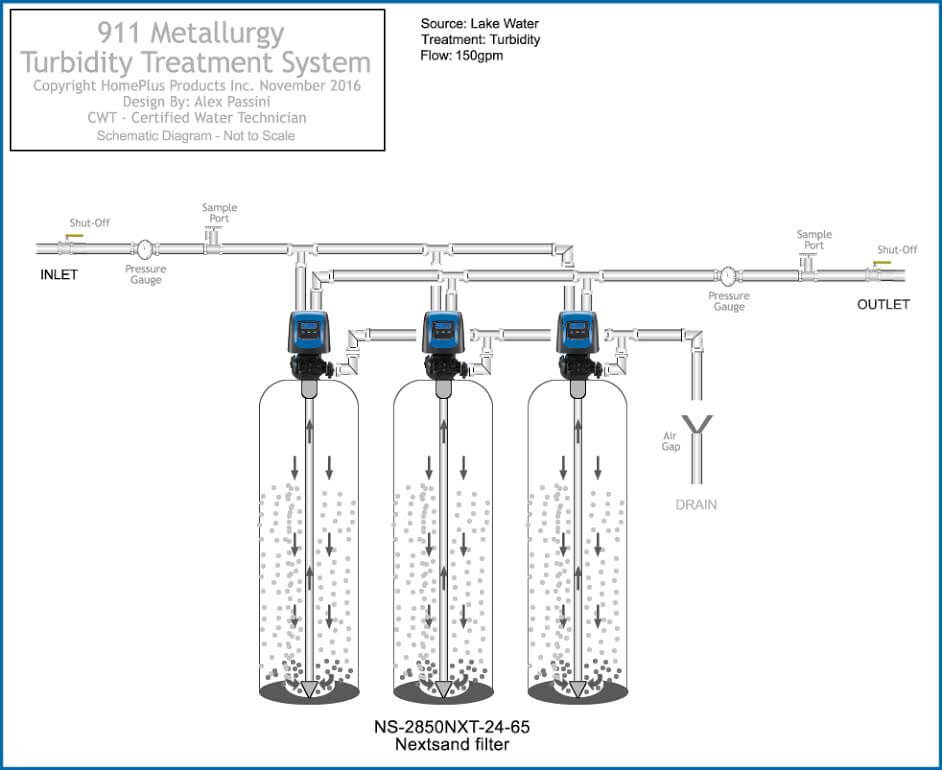
Some wastewater treatment plants have an odour control process to prevent odours affecting nearby residents. The heavy particles floc settle to the bottom and the clear water moves to filtration. These are existing industrial water treatment systems they can be sized from 10 gpm to 250 gpm.
Wastewater treatment plants work 24 hours a day 365 days a year to provide an important sanitation service that protects public health and the environment. Water is placed in a closed tank or reservoir for disinfection to take place. Text in this example.
These particles can be removed by backwashing. Sewage treatment is the process of removing contaminants from municipal wastewater. Industrial water treatment systems process flow diagram.
In the bar rack coarse solids are removed such as sticks rags and other debris in untreated wastewater by interception. The waste watersewage influent is passed from top through the activated carbon bed and the effluent comes out from the bottom. Process flow diagram for a typical treatment plant via subsurface flow constructed wetlands.
One simple and fast way is to start from ready made templates. This pfd example is created using edraw vector drawing software enhanced with pid solutionit shows the main process of waste water treatment visually. Simplified flow diagram for a biological wastewater treatment with a activated sludge process.
Create process flow diagram examples like this template called drinking water treatment process flow diagram that you can easily edit and customize in minutes. This initial charge neutralization process allows the formed floc to agglomerate but remain suspended. The combination of the first 3 steps primarily removes colloids including some microorganisms and natural organic matter nom.
6 coagulation coagulants rapidly add electrochemical charges that attract the small particles in water to clump together as a floc. At 25 ppb as i can run a system at 40 gpm however at 120 ppb as i need to reduce it down to 10 gpm with the same system to increase contact time. To the sewage treatment plant.
The specific processes used are determined by the chemical and biological raw water characteristics. Figure 1 is a process diagram for a conventional water treatment plant.


 Water Purification Process Diagram Iaoo Rennsteigmesse De
 Industrial Water Treatment Systems Process Flow Diagram
A Process Flow Diagram And Monitoring Points Of The Advanced Water
 Process Flow Diagram For Water Treatment Process Download
 Process Flow Diagram Of Water Treatment Plant Best Wiring Library
 Industrial Water Treatment Systems Process Flow Diagram
 Process Flow Diagram Of The Mudor Waste Water Treatment Plant
 A Process Flow Diagram And Monitoring Points Of The Advanced Water
 Pool Schematic Schematic Diagram


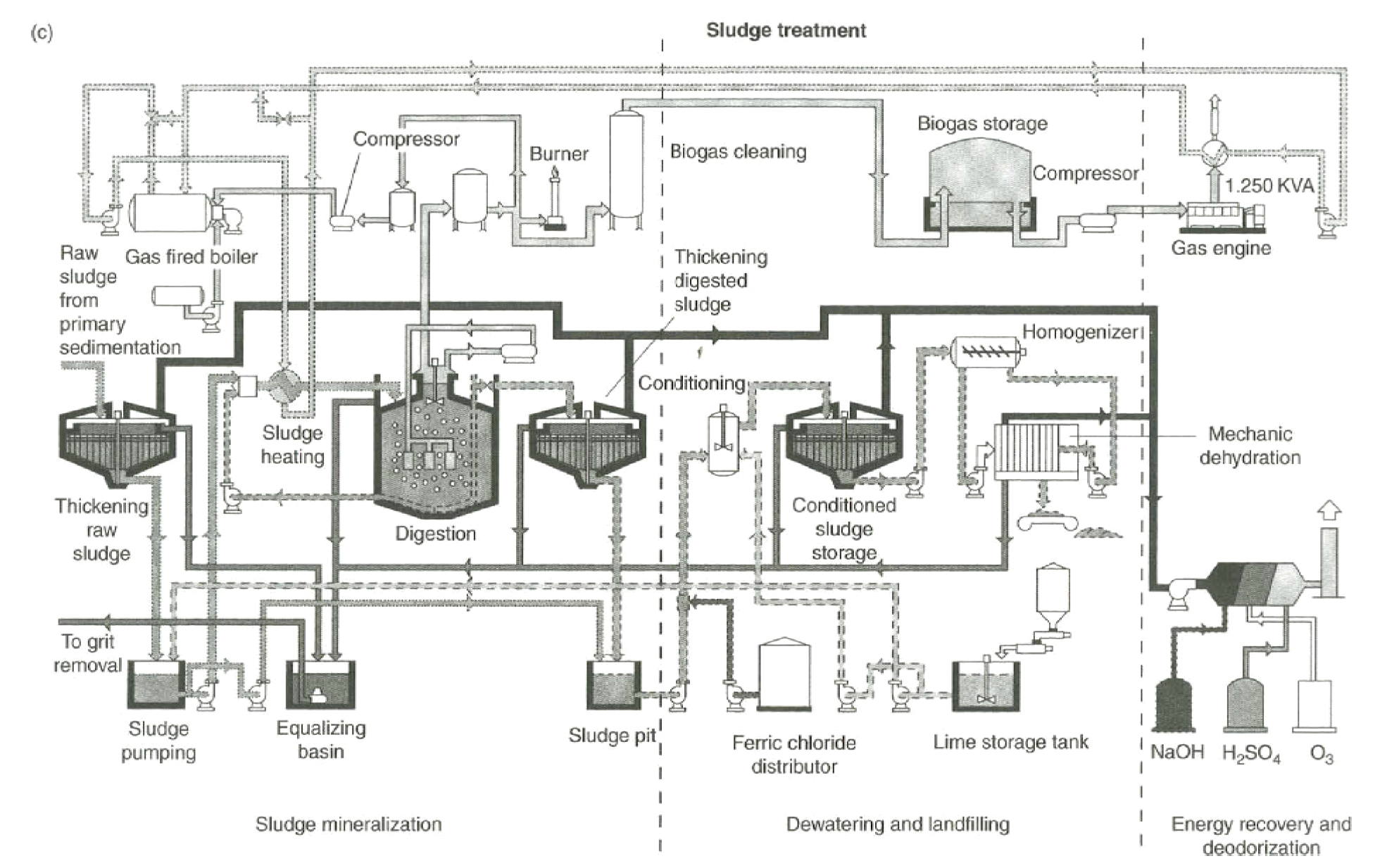 Biological And Chemical Wastewater Treatment Processes Intechopen
Figure 1 Is A Process Diagram For A Conventional Water Treatment
 Process Flow Diagram For Aspropyrgos Water Treatment Plant

 Water Treatment Wikipedia
 Quantifying The Potential Of Ultra Permeable Membranes For Water
0 Response to "Water Treatment Process Flow Diagram"
Post a Comment