Block Diagram From Transfer Function
Development of functional flow block diagrams. Example problem on how to derive closed loop transfer function from block diagram.
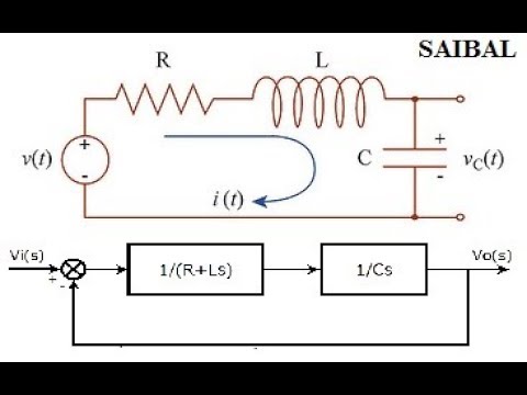 How To Draw The Block Diagram Of Any Electrical Circuit From
The first step in creating a transfer function is to convert each term of a differential equation with a laplace transform as shown in the table of laplace transforms.
Block diagram from transfer function. And then combine those block diagrams properly in order to get the overall block diagram of series of rlc circuit s domain. Note that the diagram shows both input transfer to operational orbit and output transfer to space transportation system orbit thus initiating the interface identification and control process. I suggest you start with transfer function blocks and sum blocks to match the transfer functions and sums in the diagram.
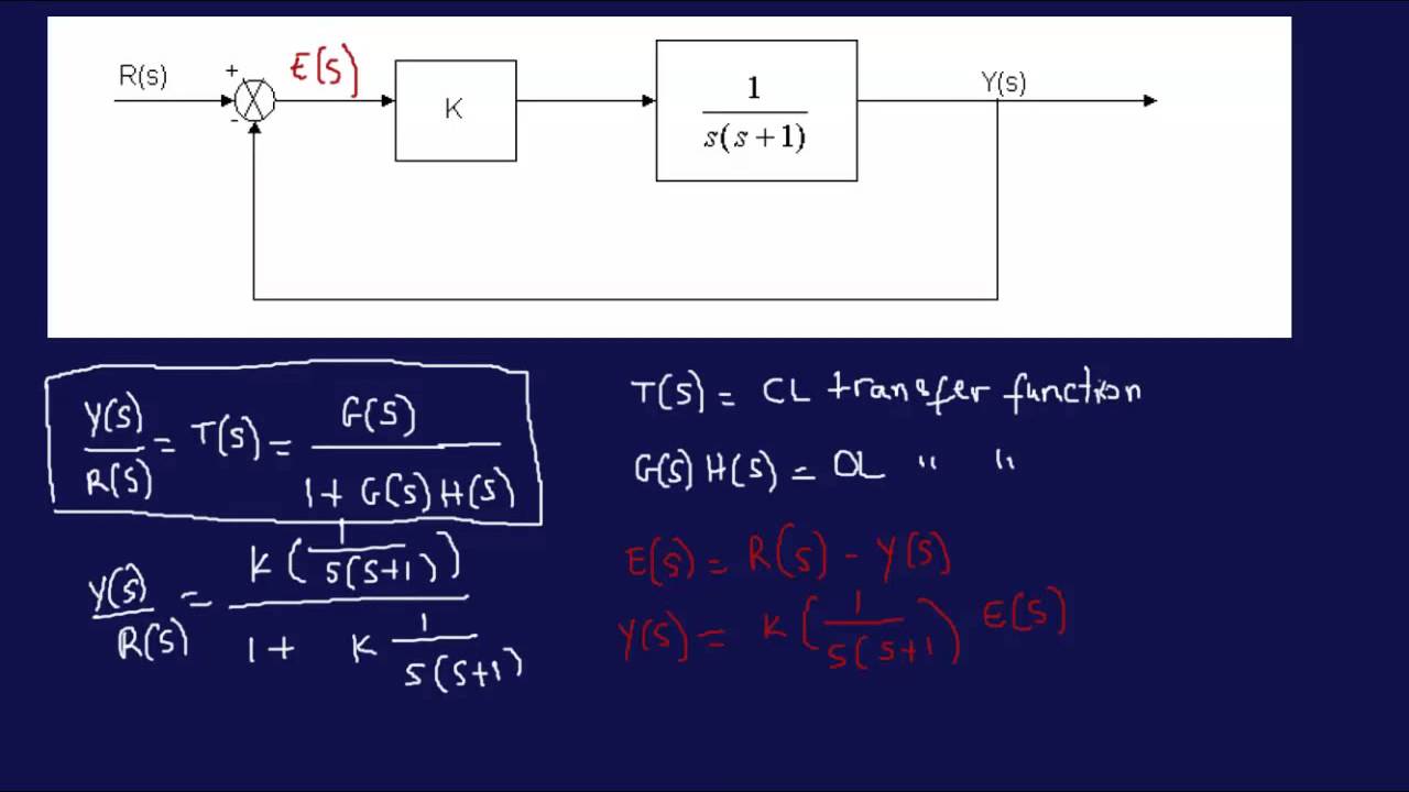
The block diagram is to represent a control system in diagram form. Derive your closed loop transfer function given a block diagram. It is easier and better to derive transfer function of control element connected to the system separately.
It is not convenient to derive a complete transfer function for a complex control system. A transfer function g s relates an input u s to an output y s. This block diagram can certainly be recreated in simulink.
It is not always convenient to derive the entire transfer function of a complex control system in a single function. This command loads the functions required for computing laplace and inverse laplace transforms. When two or more systems are in series they can be combined into a single representative system with a transfer function that is the product of the individual systems.
Signal flow graphs. This module introduces the concepts of system block diagrams feedback control and transient response specifications which are essential concepts for control design and analysis. If we have two systems ft and gt we can put them in series with one another so that the output of system ft is the input to system gt.
Block diagrams feedback and transient response specifications. Equation 1 can be implemented with a block having the transfer function frac1rsl. Block diagram gives a pictorial representation of a control.
In other words practical representation of a control system is its block diagram. I am not sure what the f blocks in your diagram refer to but if they are simply gains then you can use a gain block to represent each one. Each block in the second level diagram can be progressively developed into a series of functions as shown in the third level diagram on figure 2.
Transfer functions in block diagrams. Methods of obtaining a transfer function block diagram method. The modified form of a block diagram is a signal flow graph.
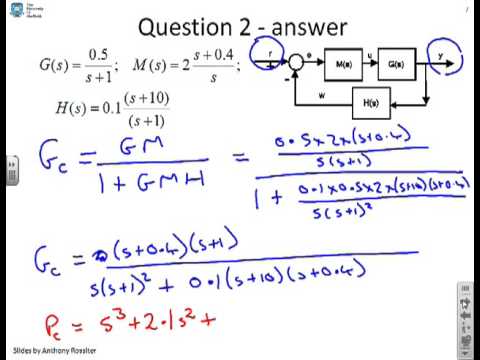
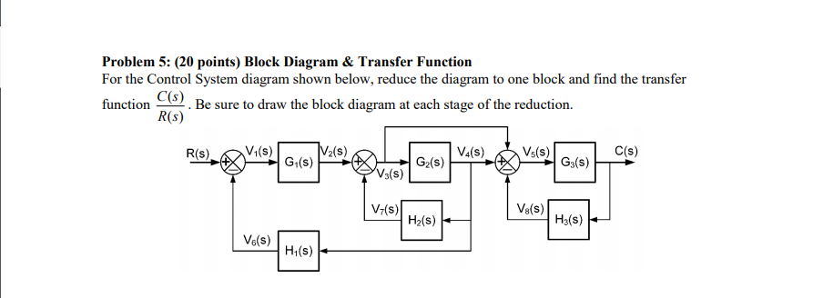 Solved Problem 5 20 Points Block Diagram Transfer Fu
 Modeling A Control System Using Transfer Functions Physics Forums
![]() Transfer Function Block Diagram Control System Block Diagram
Transfer Function Block Diagram Control System Block Diagram
![]() Transfer Function Block Diagram Download Scientific Diagram
Transfer Function Block Diagram Download Scientific Diagram
 System Algebra And Block Diagram
 Control Systems Block Diagrams
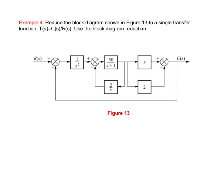
 Control Systems Block Diagram Reduction
![]() Block Diagram Transfer Function Reduction Block Wiring Diagram
Block Diagram Transfer Function Reduction Block Wiring Diagram
![]() Ppt The Block Diagram Powerpoint Presentation Id 5668999
Ppt The Block Diagram Powerpoint Presentation Id 5668999
![]() Pfd A Block Diagram And B Its Transfer Function Download
Pfd A Block Diagram And B Its Transfer Function Download
![]() Chapter 3 Dynamic Response The Block Diagram Block Diagram Is A
Chapter 3 Dynamic Response The Block Diagram Block Diagram Is A
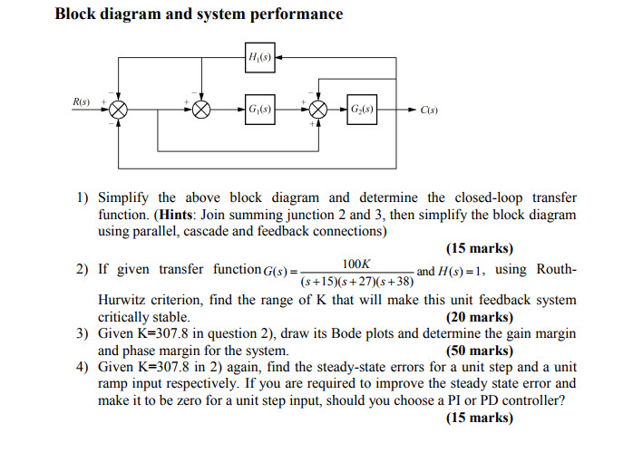 Solved 1 Simplify The Above Block Diagram And Determine
 Deriving Transfer Function From Block Diagram 1 Fe Eit Exam Review
 Reduction Of Multiple Subsystem Compatibility Mode
 Block Diagrams Of Control System Electrical4u
![]() Block Diagram Of Cnc Machine Tool Control System A Transfer Function
Block Diagram Of Cnc Machine Tool Control System A Transfer Function
![]() Functional Block Diagram Of Ic 555 Block Wiring Diagram
Functional Block Diagram Of Ic 555 Block Wiring Diagram
 Control Systems Block Diagram Reduction
 Block Diagrams 8 Tutorial Sheet On Closed Loop Transfer Functions
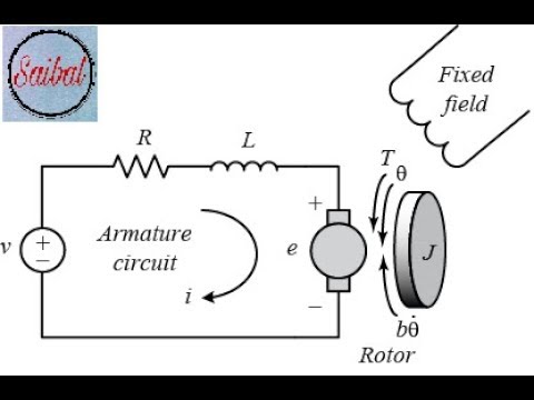 Transfer Function Block Diagram Of Armature Controlled D C Motor

0 Response to "Block Diagram From Transfer Function"
Post a Comment