Motor Control Circuit Diagram Pdf
Three phase slip ring rotor starter control power diagrams. A wiring diagram is limited in its ability to completely convey the controllers sequence of operation.
 Timer Switch Wiring Diagram Pdf Best Wiring Library
In this booklet and wherever motor control is discussed there are several terms which are used repeatedly but whose.
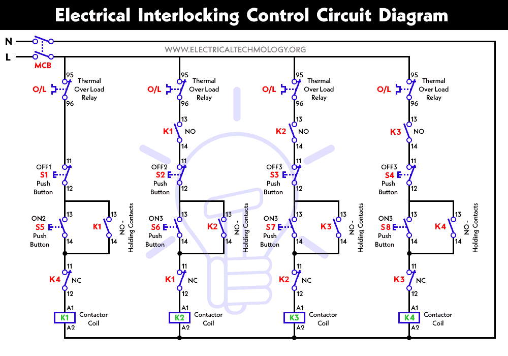
Motor control circuit diagram pdf. Wiring diagrams sometimes called main or construction diagrams show the actual connection points for the wires to the components and terminals of the controller. A very common form of latch circuit is the simple start stop relay circuit used for motor controls whereby a pair of momentary contact pushbutton switches control the operation of an electric motor. Identify common control devices from their schematic symbols.
Basic wiring for motor control technical data. Tutorial motor control o shows you how to make a small control circuit where all components are found in the component database. In this way you can always check that you have been through all steps.
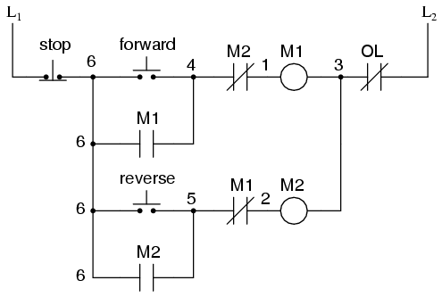
In this publication the line diagrams show the control circuits only power circuits are omitted for clarity since they can be traced readily on the wiring diagrams heavy lines. Motor control circuits are an effective way to reduce cost by using smaller wire and reduced amperage devices to control a motor. Imagine trying to wire a pushbutton station for a 100a motor using 3 awg conductors.
All motors must have a control device to start and stop the motor called a motor controller. Wire a simple control circuit from a control ladder diagram. Bold lines denote the power circuit and thin lines are used to show the control circuit.
Wire a start stop station or a single contact control device. Determine the size of wire for a group of motors. Black wires are conventionally used in power circuits and red wire in control circuits for ac magnetic equipment.
2 speeds 1 direction 3 phase motor power and control diagrams. O the project looks like pcsmotordemo1. Rev for three phase motor connection power and control diagrams.
A motor controller is the actual device that energizes and de energizes the circuit to the motor so that it can start and stop. Wiring diagrams show the connections to the controller. The finished project contains electrical diagrams panel mechanical layout and various lists.
Determine the size of the components of a motor circuit. A wiring diagram. Two speeds two directions multispeed 3 phase motor power control diagrams.
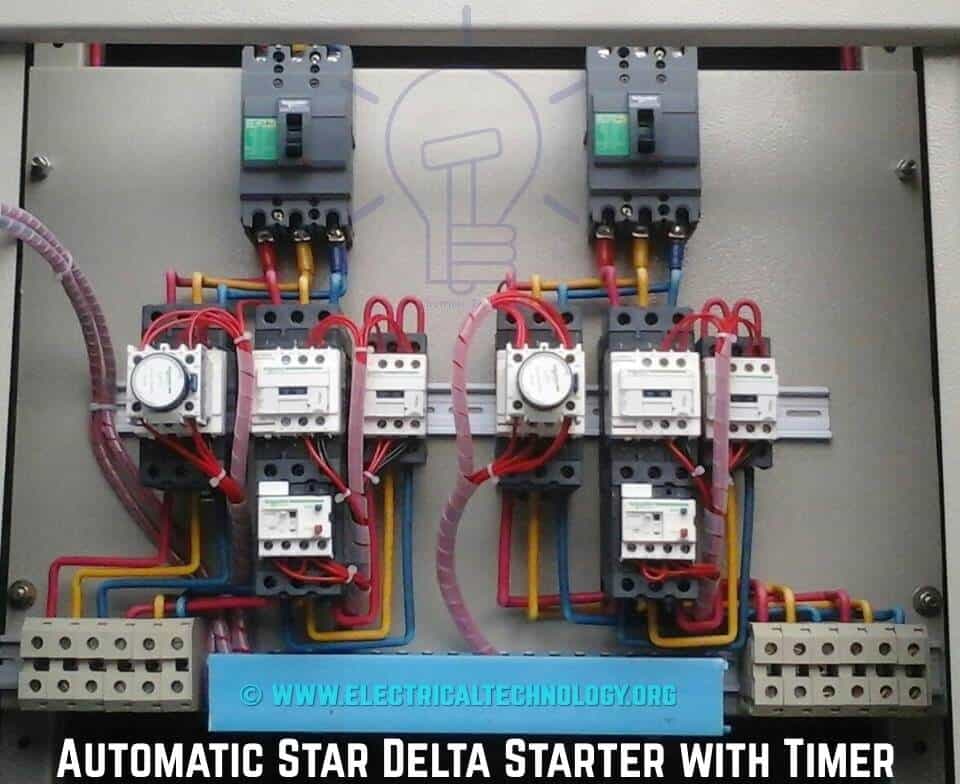
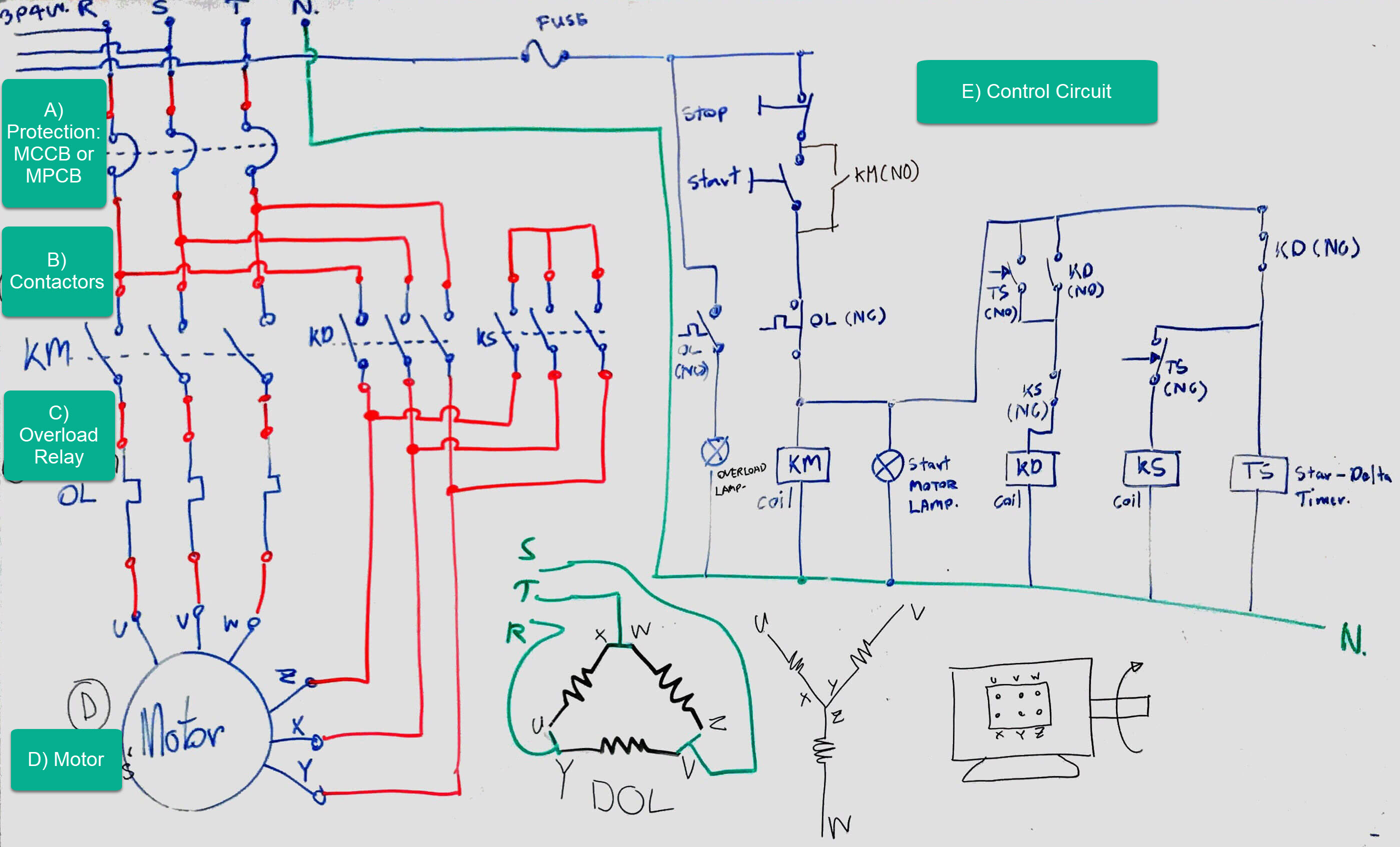
 Star Delta Starter Control Wiring Diagram With Timer Filetype Pdf
 Electronic Motor Control Diagram Great Installation Of Wiring
 Wye Delta Motor Control Diagram Toyskids Co
 Simple Washing Machine Wiring Diagram Wiring Diagram Specialties
 Bldc Motor Control Circuit Diagrams Datasheet Stepper Controller
 Vfd Wiring Diagram Pdf Schematic Diagram
 Soft Start Wiring Diagram 1 Wiring Diagram Source
 Simple Motor Control Wiring Diagram Pdf Wiring Diagram Specialties
 Panel Ac Mains Relay Changeover Circuit Electronic Circuit Projects
 Ac Motor Wiring Diagram Further Electric Motor Wiring Diagram 220 To
 Electronic Motor Control Diagram Great Installation Of Wiring
 Reverse Forward Circuit Diagram Great Installation Of Wiring Diagram
 Circuit Diagram Wii Wiring Diagram For Remote Control Toy Car 1
 Simple Motor Control Wiring Diagram Pdf Wiring Diagram Specialties
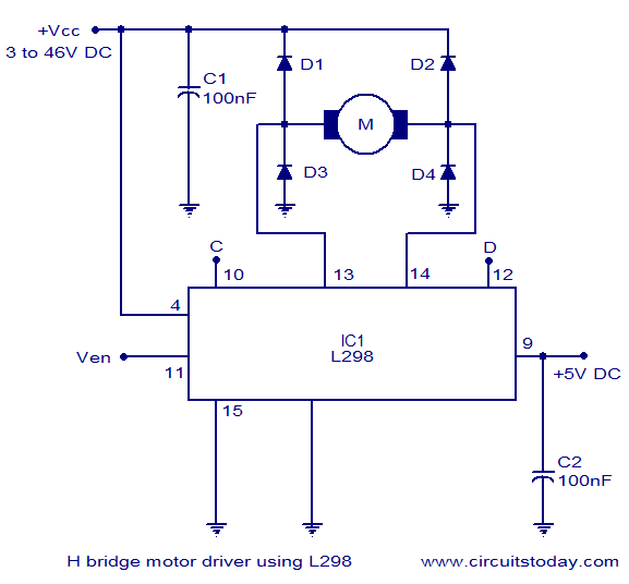 Motor Driver Circuit Diagram Iaoo Rennsteigmesse De
Electrical Motor Control Circuits Pdf Great Installation Of Wiring
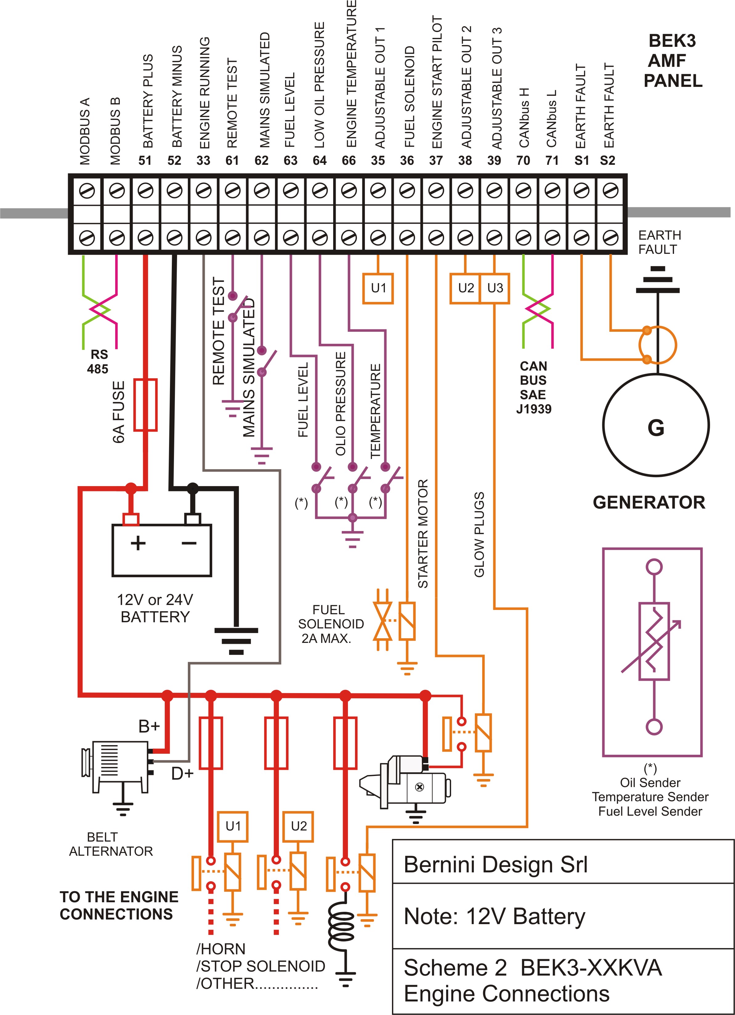 Wire Diagram Generator Schematic Diagram
 Vfd Wiring Diagram Pdf Schematic Diagram
 Star Delta Motor Control Circuit Pdf Www Toyskids Co
 Circuit Diagram Wii Wiring Diagram For Remote Control Toy Car 1
 Ac Dc Motor Wiring Wiring Diagram Database

0 Response to "Motor Control Circuit Diagram Pdf"
Post a Comment