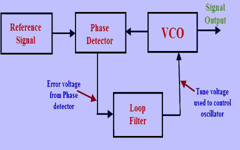
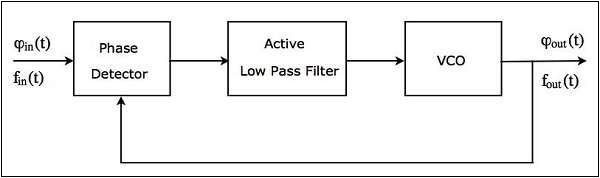
Phase Locked Loop Block Diagram
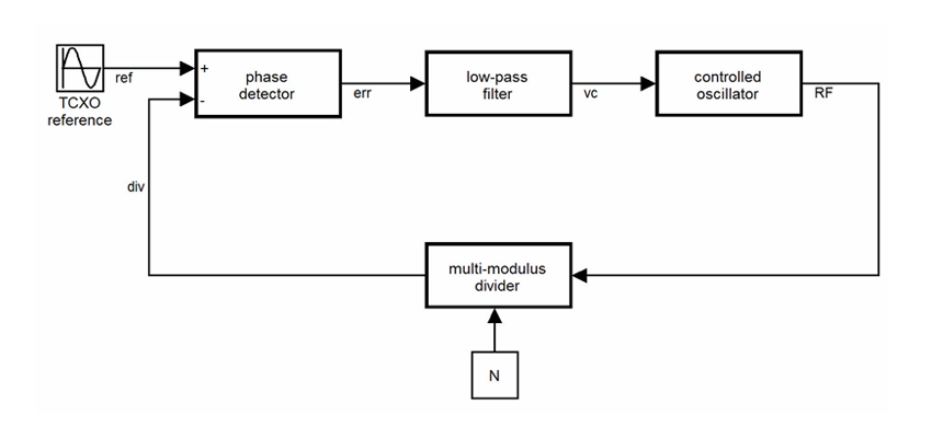
The figure shows the block diagram of the phase locked loop system in fm transmitter that consists of different blocks such as a crystal oscillator phase detector loop filter voltage controlled oscillator vco and frequency divider. The pll forms the basis of a number of rf systems including the indirect frequency synthesizer a form of fm demodulator and it enables the recovery of a stable continuous carrier from a pulse waveform.
 Silvaco Behavioral Modeling Of Pll Using Verilog A
The output of the phase detector is the input of the voltage controlled oscillator vco and the output of the vco is connected to one of the inputs of phase detector which is shown below in the basic block diagram.

Phase locked loop block diagram. 6 cd4046b phase locked loop. A phase locked loop or phase lock loop pll is a control system that generates an output signal whose phase is related to the phase of an input signal. This phase locked loop tutorial gives all the basics required for an understanding of pll technology.
Figure 1 shows a simplified block diagram of the major components in a pll. Phase locked loops pll introduction to pll. Phase aligning an internal clock to an output clock to external device extracting.
Phase locked loop pll a pll is a negative feedback system where an oscillator generated signal is phase and frequency locked to a reference signal. Typical applications of pll are. The phase locked loop approach turned out to be vastly superior to the other methods to the degree that i want to describe the method in detail so others wont pass up this terrific approach.
A phase locked loop consist of a phase detector and a voltage controlled oscillator. A phase locked loop pll is a closed loop frequency control system based on the phase difference between the input clock signal and the feedback clock signal of a controlled oscillator. The concept of phase locked loops pll first emerged in the early 1930sbut the technology was not developed as it now the cost factor for developing this technology was very high.
Generating a 1 ghz clock from a 50 mhz reference clock deskewing eg. Phase locked loop block diagram. The phase locked loop pll is a very useful building block particularly for radio frequency applications.
The simplest is an electronic circuit consisting of a variable frequency oscillator and a phase detector in a feedback loop. There are several different types. Phase lock loop basics block diagram working in communication engineering by.
It is the most important part of the phase locked loop system. A versatile building block for micropower digital and analog applications phase comparator i is an exclusive or network that operates analogously to an overdriven balanced mixer.
 Basic Introduction Of Phase Locked Loop Pll Sharing Is Loving
 Phase Locked Loop Operating Principle And Applications
 Phase Locked Loop
 Phase Locked Loop Block Diagram With Explanation Elegant 10k Ohm
 How Does The Vco Voltage Controlled Oscillator In Pll Phase
 Phase Locked Loop Block Diagram Ppt Block Wiring Diagram
 Phase Locked Loop Block Diagram Download Scientific Diagram
 Simulink Exercises For Digital Communications A Discrete Time
 Phase Locked Loop Intgckts
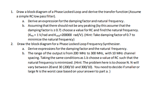 Solved Draw A Block Diagram Of A Phase Locked Loop And De
 Reference Clock Phase Lock Loop Ni High Speed Digitizers Ni Scope
 Modeling And Simulating An All Digital Phase Locked Loop Matlab
 Basics Of Phase Locked Loop Techniques Chapter 4 Synchronization
 Linear Integrated Circuits Applications Phase Locked Loop Ic
 Solved Chapter 6 Problem 23qp Solution Modern Electronic
 1 Block Diagram Of A Phase Locked Loop Download Scientific Diagram
 Phase Locked Loop Design Prepared By Harsh Shrma Parth
 Phase Lock Loop Block Diagram 8 Download Scientific Diagram
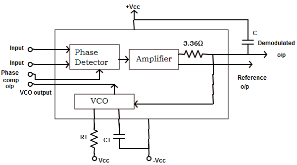 Block Diagram Of 565 Pll Wiring Diagram
 Describe The Basic Block Diagram Of The Phase Locked Loop Pll
Phase Locked Loop Design And Construction Elliot Nwaobi Elec 163
 Phase Locked Loop Wikipedia
 Phase Lock Loop Ee174 Sjsu Tan Nguyen Ppt Video Online Download
 50 Ghz Phase Locked Loop Block Diagram Download Scientific Diagram


0 Response to "Phase Locked Loop Block Diagram"
Post a Comment