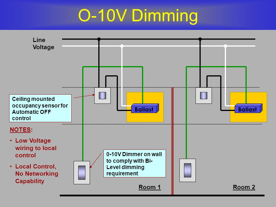
0 10v Dimming Wiring Diagram
Designed with contractors in mind the sensorworx 0 10v dimming wall switch sensor is significantly shallower than typical dimmers and sensors resulting in less crowed wall boxes. What is 0 10v dimming.
 10v Led Wiring Diagram Fuse Box Wiring Diagram
0 10v class 1 and class 2 wiring overview 0 10v ballasts and drivers are connected together by a 2 wire low voltage bus that is suitable for class 1 or.

0 10v dimming wiring diagram. Additionally versatile wiring enables usage with or without a neutral and allows reversal of line and load connections. Major motion coverage 900 ft 2 83 m minor motion coverage 400 ft 2 37 m title. Used as an early fluorescent dimming system and still used today 0 10v dimming has been adapted to become a reliable led dimming control protocol.
A 0 10v dimmer is considered analog dimming and all usai 0 10v dimming options are considered to be sink type dimming. Wiring in control4 panel wiring diagrams use the control4 8 channel 0 10v dimmer wiring diagrams along with the 8 channel 0 10v dimmer installation guide to install 8 channel 0 10v dimmers. The dimming performance of 0 10v can be impaired if the system is wired in a class 1 configuration especially if long distances of line voltage wiring are used.
It shows the elements of the circuit as simplified shapes and also the power and also signal connections in between the devices. Specification submittal page. 0 10 v is one of the earliest and simplest electronic lighting control signaling systems.
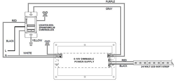
A typical 0 10v wiring diagram is shown below. Variety of 0 10v dimming ballast wiring diagram. Simply put the control signal is a dc voltage that varies between zero and ten volts.
Maestro 0 10v dimmer sensor keywords. 1 component 3 components budget friendly costly. Horizontal beam diagram 5 ft 15 m 5 ft 15 m 0 10 ft 10 ft 3 m.
Wiring t12 to led tube can bus wiring standard electrical wiring for recessed lights philips advance ballast wiring diagram emergency relay 0 10v dimming wiring diagram emergency lighting wiring diagram 10v led wiring diagram ballast wiring diagram step dimming fluorescents advance mark 7 dimming ballast wiring diagram 0 10 volt. A wiring diagram is a streamlined standard photographic representation of an electric circuit. The diva 0 10v preset dimmer provides dimming control of 0 10v led drivers fl uorescent ballasts and hid ballasts.
Lutron 010 v dimming sensing line voltage wiring low voltage wiring vs. Wiring diagrams dimming with onoff control wiring diagram using relay 0 10 v ballastdriver white white red red red white blue gray graygray red red purple purple purple. Our standard 0 10v dimming driver option is often provided standard check spec sheets and dims down to 10 at minimum light level.
Black line red switched hot grey neutral. 0 10v dimming wiring diagram 0 10v dimmer switch leviton ip710 lfz or equal for other types of dimming control systems consult controls manufacturer for wiring instructions switched hot black switched hot red typical low voltage dimming wires purple gray typical electrical panel hot black typical 120v or 277v 60 hz neutral white. Maestro 0 10v dimmer.
 Arduino Controlled Light Dimmer 16 Steps
 Arduino Controlled Light Dimmer 16 Steps
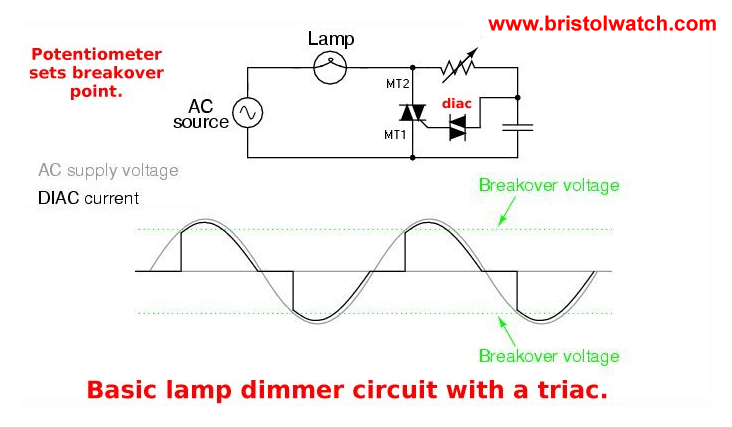
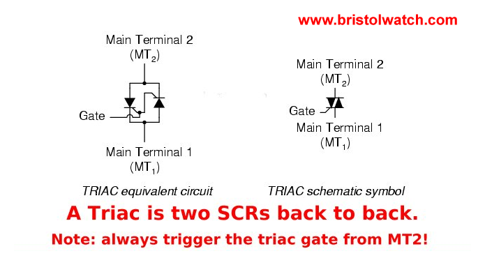 Basic Triac Scr Projects Circuits Tutorial
 12v Ac Wiring Wiring Diagram
 0 10v Dimming Wiring Diagram Led Downlight 19 11 Pluspatrunoua De
 12v Ac Wiring Wiring Diagram
 0 10v Wiring Diagram 19 Stromoeko De
 Wiring Diagram Moreover Led Light Circuit Wiring Diagram As Well
 Basic Triac Scr Projects Circuits Tutorial
 0 10v Wiring Diagram 20 13 Artatec Automobile De
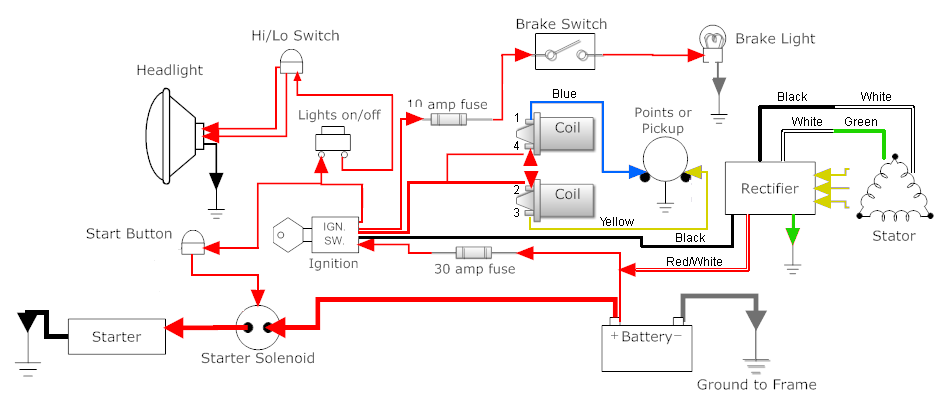 Yamaha Xs 650 Wiring Diagram Simple Wiring Diagram
 Basic Triac Scr Projects Circuits Tutorial
Switchdim Tridonic
 Diagram In Addition Led Driver Schematic Diagram Further Led Light
 Basic Triac Scr Projects Circuits Tutorial
 Arduino Controlled Light Dimmer 16 Steps
 Dimming Ballast Wiring Diagram As Well On 2wire Ballast Wiring
 Leviton 0 10v Wiring Diagram Www Toyskids Co
 Basic Triac Scr Projects Circuits Tutorial
 Yamaha Xs 650 Wiring Diagram Simple Wiring Diagram
 Yamaha Xs 650 Wiring Diagram Simple Wiring Diagram
 Basic Triac Scr Projects Circuits Tutorial
 Cmr 9 Cmr Pdt 9


0 Response to "0 10v Dimming Wiring Diagram"
Post a Comment